RS232 Connection modes
Serial Blocks/Layout
USB to RS232 (USB serial adapter)
USB to 5V/TTL RS232
USB to 3.3V RS232
RS232 to 5V/TTL RS232
RS232 to 3.3V RS232
5V/TTL RS232 to 3.3V RS232
RS232 Options
RS232 Gender Changer
RS232 Null Modem
Other
Level Shifters
Clock Generator
Power Source Selection
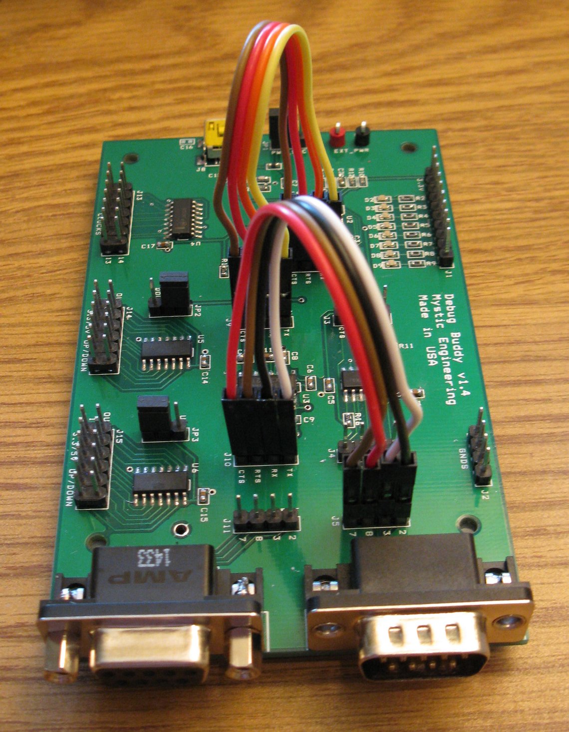
Warning: When installing or moving the 3" jumper wires or shunt plugs, always disconnect the USB cable (and external power, if connected)
Warning: When installing the 3" jumper wires, make sure the color order matches on both sides of the cables (the exception to this rule is when making a null modem, then the wires on the right side block will be crossed)
Serial Blocks/Layout
The serial port is comprised of a series of blocks, with inputs and outputs running to 4 pin connectors:
- USB serial port
- 3.3V to 5V level shifter
- 3.3V to RS232 level shifter
- DB9 (9 pin) male and female connectors
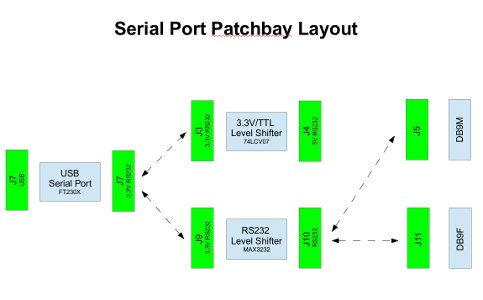
The physical locations and functions of the connectors that comprise the serial port configuration patchbay are shown in this diagram (click for a bigger version)
The serial port schematics also show how things work.
USB to RS232 (USB serial adapter)
- Connect J7 to J9
- Connect J10 to J11 (RS232, DB9F 4 pin) or J5 (RS232, DB9M 4 pin) as below
- If not using hardware handshaking, only TXD and RXD are required
To configure as a standard PC (DTE) USB serial port
- Connect J10 to J5 (DB9M 4 pin)
- Cross the TX/RX and the RTS/CTS wires
| J10 (RS232) | J5 (DB9M, DTE) |
|---|---|
| Pin 1 (TX) | Pin 2 (DB9 pin 3) |
| Pin 2 (RX) | Pin 1 (DB9 pin 2) |
| Pin 3 (RTS) | Pin 4 (DB9 pin 7) |
| Pin 4 (CTS) | Pin 3 (DB9 pin 8) |

To configure as a serial device that would connect to a PC (i.e. DCE, modem, etc)
- Connect J10 to J11 (DB9F 4 pin)
- Wire straight across
| J10 (RS232) | J11 (DB9F, DCE) |
|---|---|
| Pin 1 (TX) | Pin 1 (DB9 pin 2) |
| Pin 2 (RX) | Pin 2 (DB9 pin 3) |
| Pin 3 (RTS) | Pin 3 (DB9 pin 8) |
| Pin 4 (CTS) | Pin 4 (DB9 pin 7) |
USB to 5V/TTL RS232

- Connect J7 to J3
- 5V/TTL RS232 signals are available on J4
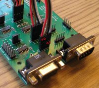
USB to 3.3V RS232
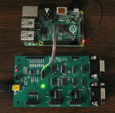
Many boards have 3.3V serial ports, including the Raspberry Pi, (pictured left), BeagleBone Black , and SolidRun Hummingboard
RS232 to 5V/TTL RS232

- Connect DB9 serial cable to J5 (or J11)
- Connect J5 (or J11) to J10
- Connect J9 to J3, crossing the 1+2 and 3+4 wire pairs
- 5V RS232 signals are available on J4
You may need to cross the wires for pins 1+2 and pins 3+4 on J5 (or J11) depending on whether the device connected to the serial cable is wired as a DTE (cross) or DCE (don't cross.)
In this configuration, the USB cable is optionally used to power the device. It is also possible to use external power rather than USB power, see Power Source Selection
RS232 to 3.3V RS232
- Connect DB9 serial cable to J5 (or J11)
- Connect J5 (or J11) to J10
- 3.3V RS232 signals are available on J9 (cross wire)
When connecting your device's 3.3V signals at J9, be sure to cross wire/null modem the signals, i.e. RX->TX, TX->RX, CTS->RTS, RTS->CTS.
You may also need to cross the wires for pins 1+2 and pins 3+4 on J5 (or J11) depending on whether the device connected to the serial cable is wired as a DTE (cross) or DCE (don't cross.)
In this configuration, the USB cable is optionally used to power the device. It is also possible to use external power rather than USB power, see Power Source Selection
5V/TTL RS232 to 3.3V RS232

- Remove both sets of jumper wires
- Connect 3.3V signals to J3
- Connect 5V/TTL signals to J4 (cross wire)
When connecting your device's 5V signals at J4, be sure to cross wire/null modem the signals, i.e. RX->TX, TX->RX, CTS->RTS, RTS->CTS.
RS232 Gender Changer

The Debug Buddy has both a male DB9 connector at J5 and a female DB9 connector J12. When connecting to a DB9 serial cable, either gender connector can be used, by connecting J10 to either J5 or J12
RS232 Null Modem


A null modem swaps the TXD/RXD lines (and also the CTS#/RTS# lines when using hardware handshaking.) This is easily accomplished by switching the TXD/RXD (and CTS#/RTS#) wires when connecting to J5 (DB9M 4 pin) or J11 (DB9F 4 pin)
Swap the two wire pairs shown to switch back and forth between standard and null modem configuration
Standard Connections for RS232 DB9M DTE (i.e. PC)
| J10 (RS232) | J5 (DB9M 4 pin) |
|---|---|
| Pin 1 (TX) | Pin 2 (DB9 pin 3) |
| Pin 2 (RX) | Pin 1 (DB9 pin 2) |
| Pin 3 (RTS) | Pin 4 (DB9 pin 7) |
| Pin 4 (CTS) | Pin 3 (DB9 pin 8) |
Connections for RS232 DB9F DCE (aka serial device)
| J10 (RS232) | J11 (DB9F 4 pin) |
|---|---|
| Pin 1 (TX) | Pin 1 (DB9 pin 2) |
| Pin 2 (RX) | Pin 2 (DB9 pin 3) |
| Pin 3 (RTS) | Pin 3 (DB9 pin 8) |
| Pin 4 (CTS) | Pin 4 (DB9 pin 7) |
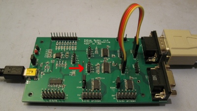
Level Shifters
There are two six channel level shifters, which can each be configured to shift from 3.3V up to 5V OR from 5V down to 3.3V.
To configure a level shifter:
- Up translate voltages from 3.3V to 5V (set Jumper to the UP position)
- Down translate voltages from 5V to 3.3V (set Jumper to the DOWN position)
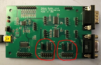
JP2 controls level shifter U5 with signals accessible at J14
JP3 controls level shifter U6 with signals accessible at J15

Clock Generator
The master clock signal originates from the CBUS0 pin on the FTDI 230. When shipped, this pin is configured to generate a 24Mhz square wave. CBUS0 can also be reconfigured to generate 12Mhz or 6Mhz if desired, using the FT_PROG Windows program available from FTDI.
These clock signals are available on J13's pins:
| 1 | 2 | 3 | 4 | 5 | 6 | 7 |
| 24Mhz | 12Mhz | 1.5Mhz | 750Khz | 375Khz | 187.5Khz | 93.8Khz |
| 12Mhz | 6Mhz | 750Khz | 375Khz | 187.5Khz | 93.8Khz | 46.9Khz |
| 6Mhz | 3Mhz | 375Khz | 187.5Khz | 93.8Khz | 46.9Khz | 23.4Khz |
| 8 | 9 | 10 | 11 | 12 | 13 | 14 |
| 46.9Khz | 23.4Khz | 11.7Khz | 5.9Khz | 2.9Khz | 1.5Khz | GND |
| 23.4Khz | 11.7Khz | 5.9Khz | 2.9Khz | 1.5Khz | 732Hz | GND |
| 11.7Khz | 5.9Khz | 2.9Khz | 1.5Khz | 732Hz | 366Hz | GND |
Note: clocks are derived from the USB signal, so they are only available when USB is connected.
Power Source Selection
Jumper JP1
- If powering the device via USB, JP1 should be in the USB position
- If powering via an external 5V supply connected to 5V (red) and GND (black) testpoint loops, JP1 should be in the EXT position